AUTOMATIC VOLTAGE REGULATION (AVR)
| Home |
| Quiet Gensets |
| Best Gensets |
| Cheapest Gensets |
| How It Works |
| AVR |
| Gasoline |
| Main |
OPERATION THEORY
An automatic voltage regulator (AVR) is a electronic device for automatically maintaining generator output terminal voltage at a set value under varying load and operating temperature. It controls output by sensing the voltage Vout at a power-generating coil and comparing it to a stable reference. The error signal is then used to adjust an average value of the field current.
Some small cheap portable generators have fixed excitation. In such machines, when an alternator is loaded, its terminal voltage Vout drops due to its internal impedance. This impedance is made of leakage reactance, armature reactance and armature resistance. The Vout also depends on the power factor of the load. That's why to maintain output within tighter limits, most models use an AVR. Note that all AVRs help regulating the output primarily in a steady state operation, but are generally slow to respond to fast transient loads. Some high-end devices, such as many Honda models, use more accurate digital DAVR with better transient response.
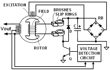 The block diagram to the right illustrates the basic concepts used in stabilizing the output of gensets with self-excited alternators. Here is how it works. When the rotor is rotated by the engine, an AC voltage is generated in the excitation winding. This AC is converted to DC by the rectifier bridge "RB"and filter capacitor "C". The detection circuit compares a voltage representing Vout with a target value and turns ON and OFF the transistor "Q". When "Q" is ON, a current flows through the field winding. When "Q" is OFF, the field current is decaying while continue flowing via free-wheeling diode "D". The rotor may include a small permanent magnet to provide some baseline current when "Q" is OFF. By properly varying duty cycle of the operation of the transistor "Q" the Vout can be regulated. Note that in theory "Q" can also work in a linear mode, but its heat dissipation will increase.
REGULATOR SCHEMATIC
The diagram below shows a generic AVR implementation. This type of circuit has been around for years. Its numerous variations are found in both portable generators and automotive alternators and are described in various patents, such as General Motor's US3376496 for 3-phase applications and Honda's US6522106.
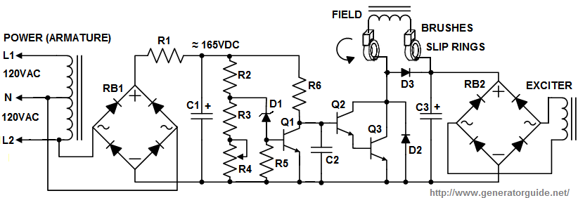
Here is a possible parts list, which is slightly modified from what was provided in this discussion: RB1/RB2=GBU6J, R1=10Ω /1W, C1=2.2μ/250V, R2=56k, R3=2.49k, R4=0...2k (pot), R5=2.49k, C2=0.01μ, D1=1N4738 (Vz=8.2V), Q1=MPSA06, Q2=2N6515, Q3=BU931T, D2,D3=1N4005, C3=470μ/200V. Of course, different manufacturers may use different configurations. For example, here you can see a reverse engineered old Generac regulator that uses SCRs and UJT. Many modern machines often use a MOSFET instead of a bipolar transistors Q2-Q3 to lower switching losses. You just need to protect its gate with an additional zener.
All information here is provided AS IS for technical reference only without guarantee and liability of any type, neither explicit or implicit, and does not constitute a professional advice- read our complete disclaimer linked below.