OPERATION OF A GENERATOR
| Home |
| Quiet Gensets |
| Best Gensets |
| Cheapest Gensets |
| How It Works |
| AVR |
| Gasoline |
| Main |
HOW IS AC VOLTAGE PRODUCED?
Any electric generator requires the following three main components to work:
- conductor to carry a current;
- magnetic field;
- relative motion between the conductor and the magnetic field.
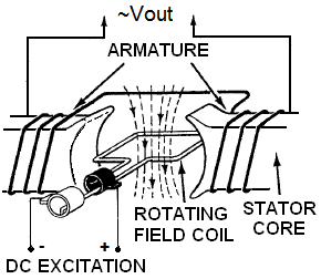 This reduces reliability of the system, causes additional power losses due to contact resistances, and requires frequent maintenance. That's why this arrangement is found only in small machines. Since the process of electromagnetic induction depends only on the relative motion between a wire and the magnetic field, in practice, most alternators have revolving field and a stationary armature. The obvious advantage of a stationary armature is that it can be connected directly to the electrical outlets.
The magnitude of induced AC voltage Vout is a function of two things: the magnetic field strength and rotation speed. In the system with one pair of magnetic poles shown above, each time the rotor makes one complete revolution, one AC cycle is generated. Since we want to produce a fixed frequency (60 or 50 Hz), in synchronous generators the field has to spin at a constant RPM. This is accomplished by the governor that maintains constant rotation of the shaft under a variety of conditions by adjusting the fuel that feeds the engine. In general, the frequency of output voltage depends upon RPM and the number of magnetic poles. If the rotor has more poles, every time two adjacent poles (a north and a south) have passed one coil, the induced voltage will have varied through one complete AC cycle. For a given rotation speed, the frequency of Vout is F=RPM×P/60, where P is the number of pole pairs. For two poles (P=1): F=RPM/60, that is for 60Hz the shaft has to spin at 3600 revolutions per minute. That's how most conventional home generators operate. Note that there is a separate class of inverter-generators, in which alternator output is rectified and then converted back to AC by an electronic circuitry. In such devices RPM is variable.
SELF EXCITATION
At a fixed speed, the Vout can be control only by varying the field strength. A permanent magnet obviously has a fixed magnetization and can't accomplish this task. That's why practical gensets normally use electromagnets in which the field is produced by a current flow through their coil.
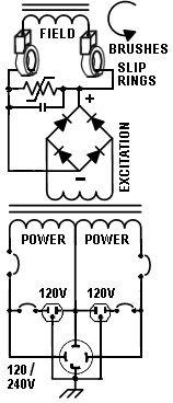 This current is driven by a separate source called an exciter, which can be external or internal. In modern alternators the electromagnet is often "self-excited". Self excitation means that the field current is created within the alternator itself. There are many different types of exciters, depending on the design and type of generator. This conceptual schematic shows an example of wiring of a self-excited portable generator. AC voltage from an auxiliary winding of the armature is rectified by solid-state diodes and applied to field coil. The current in this winding generates magnetic flux. An engine spins this assembly, which produces revolving magnetic field inside stator. The rectifier bridge can also be mounted on the rotor. Since the excitation voltage is lower than output AC and because it drives lesser currents, the issues with slip rings and brushes are minimized.
BRUSHLESS GENERATORS
A brushless system actually contains two alternators on one shaft. The larger one produces power as described above. The smaller one is the exciter. It has stationary field coils and a rotating armature with a rectifier. It produces a DC voltage which is fed directly to the field coils of the main alternator. Such a configuration is the most reliable from mechanical standpoint because brushes and slip rings are not used. However, brushless gensets without AVR provide poor power quality.
FIELD FLASHING
As we have seen above, for self excitation we need AC voltage in the armature. This voltage obviously appears only when an alternator starts. But how does it start before its armature produces voltage? Normally, the initial magnetic field is induced by residual magnetism in electromagnet's cores. When the genset shaft starts spinning, this residual magnetism causes a small voltage to be generated in the armature. It strengthens the magnetic field and allows the coil to generate a higher voltage, which is turn increases the flux, and so on. This process continues until the output voltage reaches the required level.
The residual magnetism of the electromagnet core may be lost or weakened by external magnetic fields from any source, or by non-operation for a long time. If the core lost its residual magnetization, the engine will spin, but no output will be produced. In this case, to start the device you may need to do so-called field flashing. If your owner's operation manual does not provide recommendations for your particular model, here is a typical procedure. First of all stop the engine and turn the circuit breakers off. Then disconnect leads of the field coil from the brushes (note the polarity of the leads). Then briefly apply voltage from an external 12V battery or another DC source in series with a current limiting resistor to the field coil while observing polarity. You can use 10-20 Ohm 25W resistor or a light bulb. Be sure to connect "plus" of the battery to the lead that was attached to the positive brush. Allow the field to be flashed for some 10 seconds, then remove the external voltage source. Finally, reconnect the coil terminals. Some models may provide automatic field flashing. For example, in the devices equipped with electric start, initial field can be created by a current driven from a starting battery during engine cranking.
When the load on a generator varies, its terminal voltage changes because of internal impedance of the windings. The only practical method to keep it constant is to control the amount of current flowing through the electromagnet's coil. For the details and some schematics see our tutorial on how automatic voltage regulators work.